Sudspave® installation process
The following generic guidance must be read in conjunction with the specific project specification within the contract documents
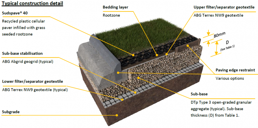
1. Install the specified lower filter/separator geotextile and subbase stabilisation onto the prepared subgrade formation.
2. Install the specified subbase and edge restraints.
3. Install the upper Terrex NW9 filter/separator geotextile on top of the subbase.
4. Install the specified bedding layer to a uniform thickness.
5. Ensure an accurate right-angled Sudspave laying pattern by setting-out the site using pins and string-lines. Check the lines regularly for accuracy. Start installing the pre-assembled Sudspave panels (4 units/m²) by placing the webbed face downwards onto the bedding layer. Place the panels with the T-shaped lugs facing in the direction of laying on the two leading edges, with the clip-slots on the reverse-edges.
6. Progress across the site in rows by slotting panels together in a downward motion, ensuring that the 8 self-lock clips-slots engage fully with the T-shaped lugs on adjacent panels.
7. Avoid starting more than 2 new rows of panels prior to completing the row which is in progress. Avoid installing in a diagonal pattern too far ahead of completed rows. Regularly check and adjust the completed leading edge to ensure that it is straight. It is recommended that protective gloves are worn to avoid abrasions during installation.
8. Individual paver units can be separated if required. Insert the tip of a flat-blade screwdriver between each side of T-lug and the slotted paver-face in turn. Gently twist the blade to dislocate each clip-lock & lug, whilst lifting the slotted unit up and apart. Do not force clips open or pull pavers apart as this will break clips.
9. Sudspave can be cut to fit around curves or obstacles using a hand-saw or disc-saw. Using cut-pieces which do not have integral T-lugs & clips should be avoided wherever possible. However, if use of small pieces is unavoidable, these must be securely attached to adjacent panels using strong cable-ties or appropriate screws.
10. Installation of parking bay/line marker inserts is best done prior to filling cells. Push markers into the round cells until they click and lock into place. Rotate slightly to fit if required.
11. Fill the cells with the free-draining 60:40 sand:soil rootzone blend, so that the finished level will be 7mm – 10mm below the top of the cells after natural settlement. If placing pavers and filling the cells simultaneously, it is important to keep bulk materials and vehicles away from the leading edge to avoid distortion. It is strongly recommended that wherever possible, vehicles should not be driven on the filled surface until a stable grass root structure and vigorous healthy grass cover have thoroughly established. Unless it is a specific design requirement, do not over-fill or surcharge the cells. Topping-up of the rootzone within the cells after installation is not recommended.
12. Apply the grass seed at the supplier’s recommended rates. Irrigate the surface regularly or as specified during the seed germination and establishment period.
13. A routine management and maintenance programme to keep the grass healthy, and the surface in good condition and free of debris, will help to sustain the porosity, quality and longevity of the system. A normal grass-cutting regime is suitable for the system and conventional grass cutting equipment can be used on the Sudspave surface. A regular and routine seasonal fertiliser programme will help to sustain and maintain healthy, wear tolerant grass cover.
Notes:
a. Advice on subgrade CBR% strengths, ground conditions, and construction over weak ground is available from ABG.
b. Alternative ABG stabilisation geosynthetics may be used in lieu of ABG Abgrid geogrid. These include ABG Gridtex Type 2 high-strength woven geotextile or ABG Abweb geocells. If the subbase stabilisation is omitted, the total subbase layer thickness (‘D’ on Table 1) is typically increased by a minimum of 50%.
c. A permeable open-graded (reduced-fines) aggregate is recommended, such as DTp Type 3 low-fines roading aggregate, or BS 7533-13:2009 SuDS aggregate (4/20 or 4/40). However, where a conventional DTp Type 1 subbase is to be used, it is essential that a drainage system such as ABG Fildrain is incorporated. Specific advice is available from ABG.
d. Maximum subbase particle size should match minimum subbase thickness, but must not exceed 75mm diameter. For subbase thicknesses of around 100mm, a minimum 37.5mm particle size should be adopted to allow effective installation of the Abgrid.
e. Typical paving edge restraint solutions include: concrete, timber, railway sleepers, steel and heavy-duty plastic.
f. The subbase must be overlaid by a Terrex NW9 geotextile to provide separation, enhanced water treatment function and prevent migration of the bedding layer.
g. Rootzone for the bedding layer and cell infill should be free draining. A loamy or clay based soil with low permeability, or site-won material, is not suitable. A more sustainable and hard-wearing grassed surface will be achieved if the cells are under-filled with rootzone so that the crowns of the grass plants are established and protected below the tops of the cells. Natural settlement of the rootzone to its final level within the cells is preferred and the use of compaction machinery on the filled surface is not recommended.
h. The specified grass seed mixture should consist of hard wearing, low-maintenance and drought tolerant species which are capable of rapid recovery after wear. Fertiliser will help to establish and maintain a healthy grass sward which is capable of sustaining traffic. Ensure that the surface is well irrigated in accordance with local and seasonal weather conditions.
i. The maximum advised gradient for vehicular trafficked applications is generally 12% (1:8) 7°. For Disabled access applications, a maximum of 8% (1:12) 5° is suggested.
j. When designed in accordance with the recommendations, Sudspave complies with BS8300:2009 : “Design of buildings and their approaches to meet the needs of disabled people” – Code of Practice (ISBN 9780 580 57419) & Building Regulations Document ‘M’ Section 6.
k. All stated dimensions & weights are nominal and in accordance with manufacturing +/- tolerances.
l. The recommendations in this document are only suitable for use with ABG products.
Table 1: Sudspave® typical DTp Type 3 sub-base thickness (D) requirements – refer to specific construction drawing
| Application/Load |
CBR (%) strength of subgrade soil (Table 2) |
(D) DoT sub-base thickness (mm) |
Abgrid Geogrid |
| Light vehicles with emergency HGV access |
6+ |
100 |
20/20 |
|
=4-6 |
150 |
20/20 |
|
=2-4 |
175 |
30/30 |
|
=1-2 |
275 |
30/30 |
| Light vehicles with one HGV per week |
6+ |
150 |
20/20 |
|
=4-6 |
200 |
20/20 |
|
=2-4 |
250 |
30/30 |
|
=1-2 |
375 |
30/30 |
Table 2: Field guidance for estimating subgrade shear strengths
| CBR (%) |
DCP Result 1 (Sandy Soils) |
HSV Result 1 (Clayey Soils) |
Tactile (Clayey Soils) |
Visual (Clayey or Sand Soils) |
| 1 |
<1 |
<30 kPa |
Easily indented by fingers |
Adult standing will sink >30mm |
| 1-2 |
<1 |
30-60 kPa |
Indented by strong finger/thumb pressure |
Adult standing sinks 10-30mm |
| 2-4 |
1-2 |
60-120 kPa |
Cannot be indented by thumb pressure |
Utility truck ruts 10-25mm |
| 5-7 |
2-3 |
120-200 kPa |
Can be indented by thumb pressure |
Loaded construction vehicle ruts by 25mm |
| >8 |
>3 |
>200 kPa |
Difficult to indent by thumb nail |
Loaded construction vehicle ruts by <10mm |
Note: 1. DCP results are expressed as blows per 100mm penetration. HSV results are expressed as “undrained shear strength” or Cu