Project Description
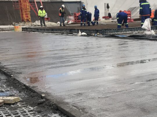
A huge extension to the existing Saldanha oil storage facility was commissioned by Oiltanking MOGS Saldanha, a JV of Oiltanking Gmbh, MOGS Ltd and Industrial Development Corporation of South Africa. Now the largest crude oil storage facility in the southern hemisphere, it is strategically situated 130km north of Cape Town in the Western Cape. The contractor, WBHO, commenced on site in September 2016 and 9 of the planned 12 new tanks are now online. Covering an area of 24 football pitches and at 17m high, they are capable of storing a massive 13.2 million barrels of crude oil.
The Challenge
Each 110m x 110m tank can store 175,000m3 crude oil. Leakage cannot be tolerated in this ecologically sensitive area. The leakage rate of oil through any imperfections in the primary lining, and subsequently through the concrete base, is governed by the hydrostatic head of the 17m of crude oil; the higher the head, the higher the leakage rate. A secondary liner would reduce or eliminate the subsequent leakage rate into the ground, however, the leakage rate of the secondary liner is also dependent on hydrostatic head. It is therefore essential to maintain a void with sufficient redundancy between the two liners, to both remove the hydrostatic head from the secondary liner whilst also collecting and draining leakage through the primary. In line with best practice a double liner had initially been designed with a 150mm no‐fines concrete leak collection layer. Since the tanks are founded on rock the cost of excavation to accommodate the 150mm extra no‐fines concrete was significant. The consulting engineer, BSM Baker, needed to find a thinner solution.
The Solution
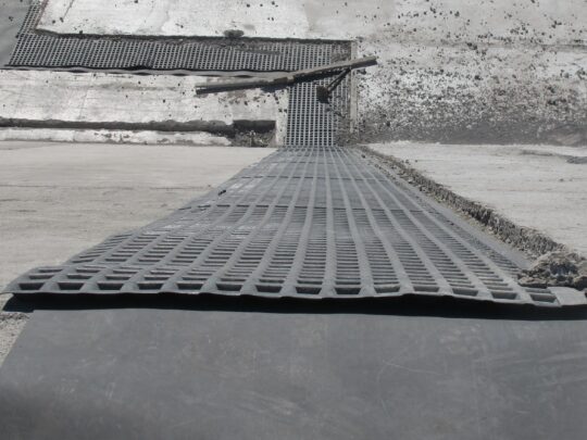
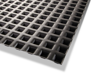
ABG Leakdrain S20U, with just 20mm thickness, gave substantially higher performance than the 150mm no‐fines concrete originally considered. With ample void space and aligned flow passages, ABG Leakdrain S20U exceeded the calculated drainage capacity of the no‐fines concrete. In addition, sufficient void remained, reducing the hydrostatic head on the secondary liner to almost zero. The cuspate geometry of the ABG Leakdrain S20U allowed flow in all directions, lowering drainage impedance. To speed installation, ABG Leakdrain S20U was prefabricated into 3.23m x 47m panels prior to shipment. After installation and sealing of the drainage panels, a concrete screed layer was cast into them and topped by a slip layer. Finally, the concrete base slab with rebar was cast, forming a drained slab such that the compressive load transmits directly through the concrete to the rock foundation.
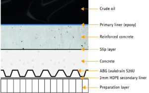
Tank base construction cross section ‐ 150mm no fines layer replaced by 20mm Leakdrain to provide a drainage detection void beneath the primary liner and reduce the basal excavation depth required over a large area.
Each container load of ABG Leakdrain S20U (6,000m2) saved approx. 60 wagon deliveries of no‐fines concrete, substantially reducing emissions in this environmentally sensitive, coastal location.
The ABG Service
The ABG Leakdrain S20U sheet was manufactured with a 100mm selvedge for on‐site extrusion welding to create a low permeability barrier. Permeability and leakage volume calculations were provided plus design assistance, installation guidance and additional MQC production checks.